DIY Ionophone
I always want to build Ionic horn tweeters but it was a time issue, because it needs a lot of research how to built the quarz cell, making the electrode, looking for some ceramic spacers and find a aluminium horn in acceptable size to fit the chasis. Electronic is the simplest part in this case. I have used the original plan of DuKane's Ionovac. Sure the power supply need some minor modifications. Here in Europe we have 230V main power which make it easier.
In the Video beside you hear the Ionophone and I am adjusting the flame size. The camera cannot capture the different loudness because it have a automatic volume control, but you can see how the flame change.
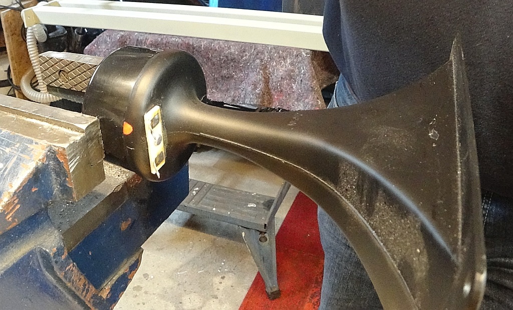
The Horn
In our big online auction house with the "e" in the beginning I coincidentally found new old stock Realistic aluminium horns (40-1228A) from the seventy's for a very resonal price. The were also used by Sony and Yamaha with their own logo. The Horn is 180mm in height and 80mm wide. It was rated to go from 1,5khz up to over 20khz.

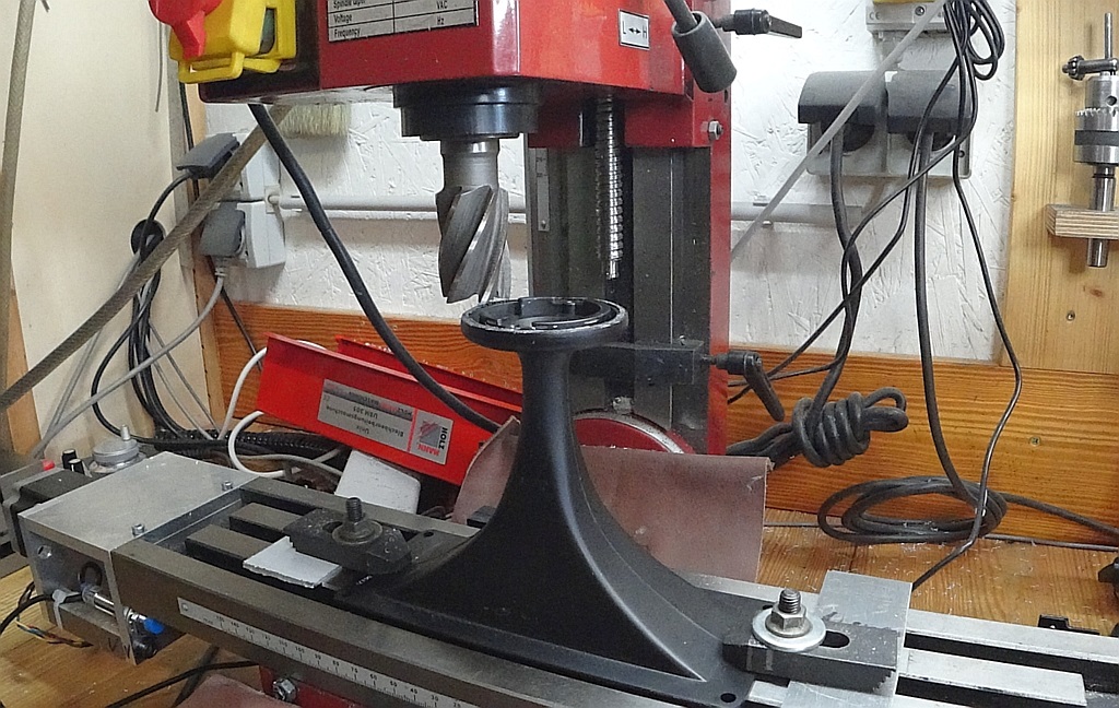
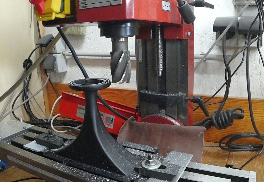
Horn modification
The Horn has to be modified a little so that it can be mounted on the chasis. The original voice coil is not needed any more and goes to the trash. To modify it you need a mill to make it flat on the back.
Cermic spacer
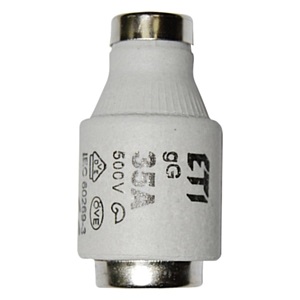
The ceramic spacer between the horn and the quarz cell is a big household fuse. They are indeed very good desined for our purpose. The hole in the ceramic is conical from 8mm in the beginning to 13mm on the other end. The back of the fuse fit perfect in the end of the horn. The ceramic is glued with high temperature silicone (300°) to the aluminium horn.
I am using 9mm diameter quarz cell, so the 8mm end of the ceramic has to be grinded (with diamond grinder) to fit with the 9mm cell. I have no pictures from all this work but you can see it properly in the chasis pictures.
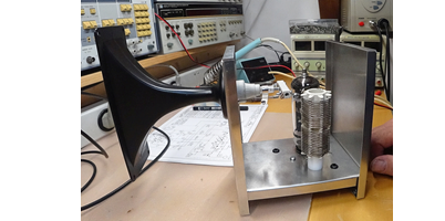
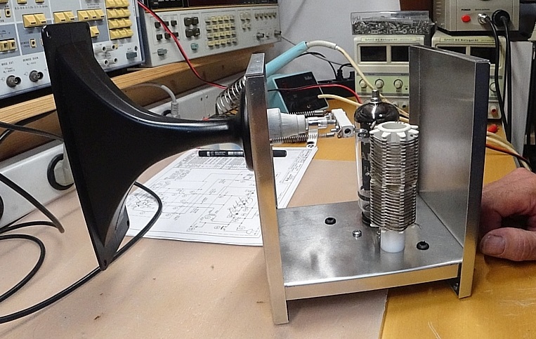
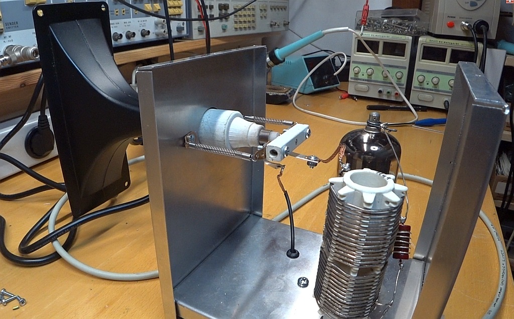
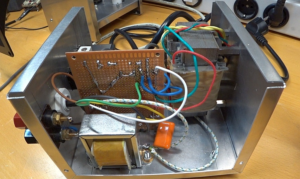
Chasis
The chasis is made out of aluminium, nothing fancy.
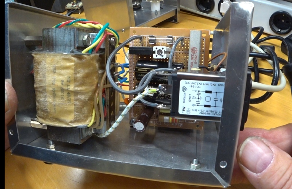
Power supply and modulation
The power supply is very simple. The anode HT comes direct from the main. The used PL519 tube need 40V heater so this is the big transformer you see in the chasis. Modulation transformer is also easy to find. Any good quality audio transformer for SE Amplifiers will do the job. The original design has a transmission ratio 1:33. Screen grid bias is about 5mA so there is no need for a large audio transformer. For the prototype I used Visaton TR84 with the 6W tap on the secondary. This can be further improved but it is sufficient to test the tweeter.
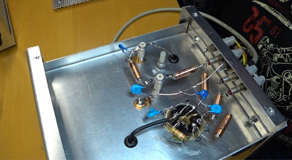
Circuit
As I mentioned before I used exactly the old plan here in the version for 230V main power.
I replace C3 located before L7 with a variable cap 5pf to 50pf. This is the cap to control the flame size, for starting it must be in the 50pf position.
Be aware that there is no transformer for separating the main voltage with the circuit. When testing a line separation transformer is needed. Without such a transformer you cannot measure in the circuit, you blow up your instuments immidiately. Also it is exrem dangerous to work without a line separation transformer. I always use one when I am testing.

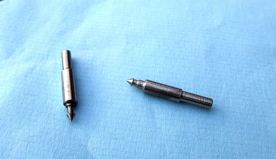
Quarz cell and electrode
This is the part which make me a lot of grey hairs. I experimented with different glas tubes, grind them on the lathe. Therefore I had to buy diamond drills and grinding stuff.
To make it short, it took me 4 weeks to realize that with my tools I am not able to grind or drill the glass tubes properly. So I was searching for a company which was willing to make low quantities. At the end I found one.
Electrodes are no problen I make them by myself out of Kanthal® .

At the end the first test
Beside a short video testing the first prototype with a sine wave generator.
My camera is not able to record the audio properly because of the build in automatic volume control and noise cancelling.
Videos in German explaning the building process. You find them in the Video section linked to Youtube.
... and how is the performance with Music ?
Here is a short Video of the tweeters.
I have build a matching bass/midrange unit with a Visaton AL130A driver.
The driver is mounted in an reflex enclosure tuned to 45Hz.
The reflex tunnel goes toward the bottom.
Have fun....